Building the Meowzor robot
As part of the third year design studio class for Computer Engineering at UBC, I worked on a group project using a FPGA, electronics, and other pieces. We had to pick a project idea and then build it in a 4 month term as a group of 3 or 4 (we were 3). The group I was in built a robot called Meowzor that points a laser in front of a cat, using an object detection model (MediaPipe) to find where the cat is and commanding the laser robot accordingly.
You can see our presentation video here:
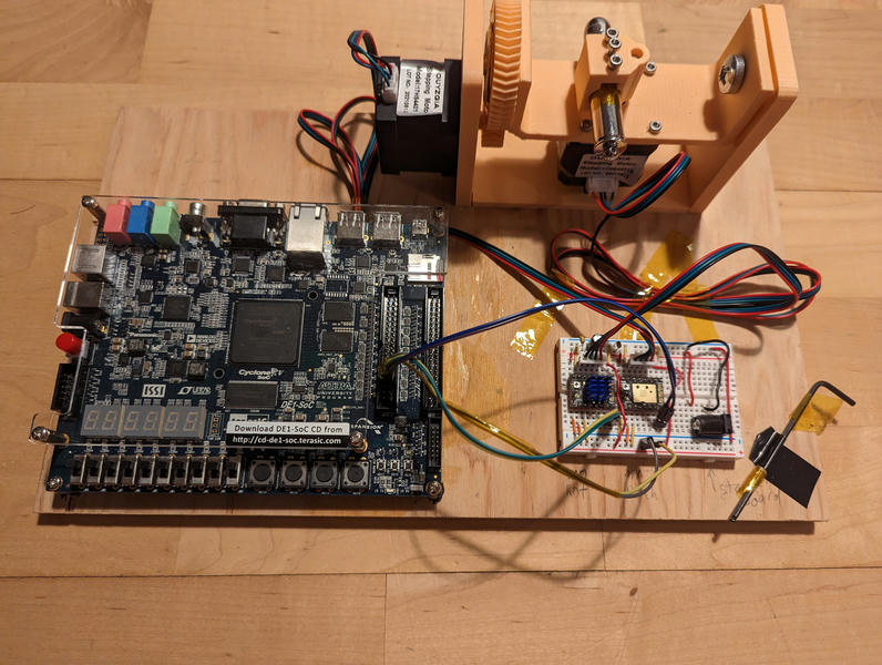
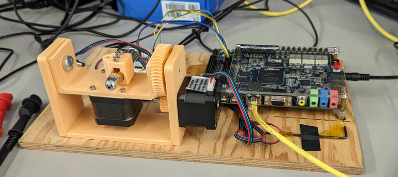
This is the robot itself:
The piece I built was all the robotics parts: the boundary is at the API layer between the robot and the cat-detection service, accepting move-to commands over HTTP. This meant that I wore a lot of hats, from Rust and embedded Linux to FPGA dev, electronics and mechanical engineering. It also meant that I had to make decisions to avoid as much hard complexity as possible in order to ship a big pile of stuff on time.
This post reviews all the technical decisions made in the robotics part of the Meowzor project.
This is the architecture diagram of the components I worked on:
We use stepper motors because they are precise, pretty fast, cheap, and easy to integrate with.
The overall design is that meowzor-control receives position requests,
generates step schedules, then gives them to the Nios II firmware to execute.
Hardware
Mechanical parts
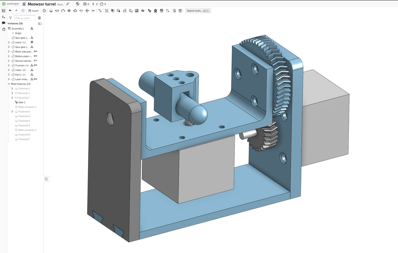
The robot consists of a two axis motion stage providing both pitch and rotation movement, with the rotation motor attached to a trunnion. This overall design was chosen because it makes it possible to easily support both sides with bearings and ensures that we definitely have enough motor torque. I built the frame out of three pieces to get optimal print orientation on the bearing pockets, and joined the pieces with dovetails.
The trunnion was designed so that the axis of rotation of the trunnion runs through the middle of the motor shaft such the laser rotation has reasonable kinematics. The laser is mounted to the rotation motor with a coupling that has two retention screws and one screw to actuate its power switch. Ideally it would be directly on top of the motor shaft but that's not feasible with the long-shafted motors we had.
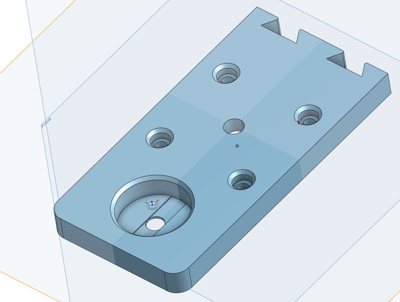
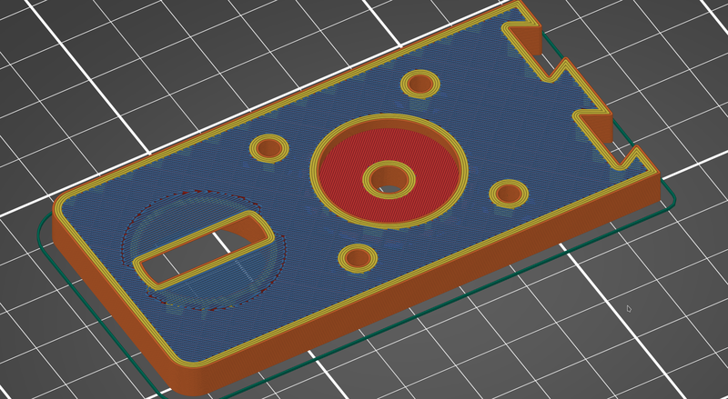
One cute trick used in the design of the printed parts is to force bridging by cutting an area out of an overhanging region with a hole in it, turning it into two bridgeable regions, which are printed as bridges. Then, on the next layer, the cut out area is bridged in a perpendicular direction, and the hole comes out nicely.
I found various design errata in the parts I printed, mostly wrong tolerances, but they were all patched up with some combination of kapton tape, scrap paper, and a drill. I tried to follow the process of fixing the thing until I learn everything I need to to do the next revision, but it turned out that one was good enough to just continue with.
I designed the mechanical parts in Onshape and printed them in PLA on the Prusa i3 MK3.
Electronics
The robot uses TMC2209 stepper driver boards. We had one fail, which may have happened due to motion with the power off, us forgetting decoupling capacitors on the motor power rail (oops! kinda important; these were put in later) or gremlins.
The intended decoupling design of the TMC2209 is to have at least 50μF of bulk decoupling and a ceramic capacitor on each motor power pin. I used a 200μF capacitor on the motor power line.
We used the GPIO pins of the DE1-SoC board, which are only documented properly in the schematic. They are 3.3v standard so work seamlessly with the stepper drivers. This is the pinout of that header, extracted from the schematic and annotated:
Computers
In my program we use a DE1-SoC Intel Cyclone V FPGA development board for pretty much everything, and everyone has one. This board has these relevant features:
- ARM Cortex-A9 dual core hard processor
- 1GB DDR3 memory
- More Cyclone V FPGA than you need
- Ethernet
- GPIOs attached to the FPGA fabric
My goal was to make the hardware and firmware as simple as possible because they suck to work on, with the most basic FPGA system taking 6 minutes to synthesize with Intel Quartus. The less time I am waiting for a compiler, the more sane I will be. Firmware sucks slightly less to work on, but is also a wreck of a mess due to Intel tools, and the Nios II only can run C/C++ due to the LLVM port being dead.
RISC-V would be viable if it weren't for the requirement to integrate nicely with the Intel tools. It looks like there's some movement on making this work, but I didn't want to take the risk on it. Intel itself has made a RISC-V Nios processor, but I was under the (apparently false?) impression that it was not available except in Quartus Pro licenses which we don't have.
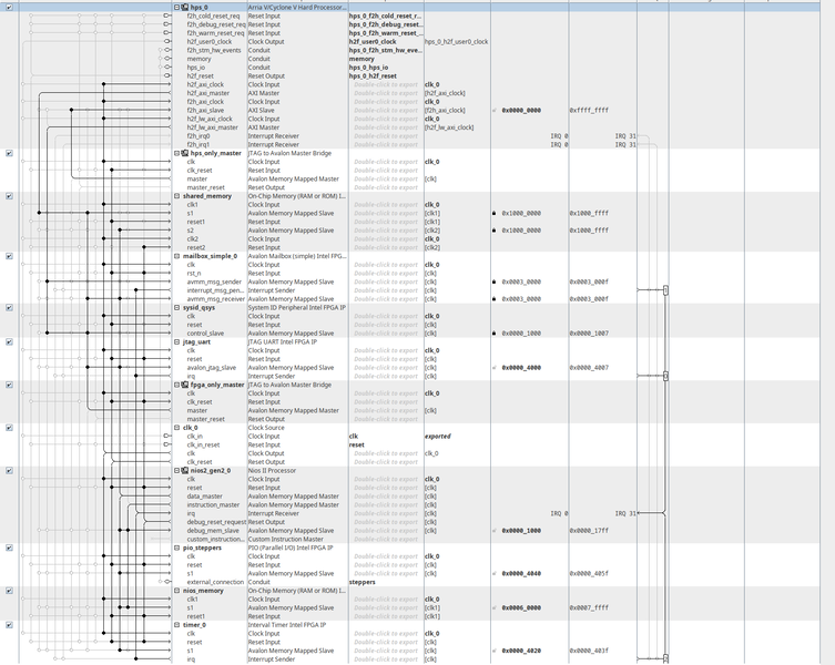
Thus, what I did with the hardware is to try to shove everything nontrivial up-stack as much as possible. I used a Nios II soft core on the FPGA fabric to generate step signals, since it is easy to integrate with Quartus Platform Designer (Qsys) and thereby spend less energy on hardware. Platform Designer deals with all the annoying pieces of putting together a computer system such as address decoding and other kinds of wiring things up.
In the end basically all of the hardware is just the reference design from the DE1-SoC materials and various integration in Platform Designer, which is a win because I mostly didn't have to debug it. This is somewhat of a buried tip, but it's an important one: there doesn't seem to be an easy way to get all of the memory configuration and other board specific details correct inside of Platform Designer short of just copying the Terasic-provided reference design.
The final code on the FPGA fabric is a Nios II processor with a timer, a mailbox to the hard processor, shared memory with the hard processor, and a GPIO controller connected to some FPGA I/O pins.
Firmware
A mailbox in hardware is an inter-processor communication primitive: it takes a memory address and a command from the sending processor and interrupts the receiving processor when something new is received. The receiving processor can then take the address out of the mailbox, copy the memory out, then empty it for the next item. Optionally the sending processor may be interrupted to inform it of it being empty.
In the case of the Intel IP, the mailbox has a capacity of one item, and the interrupt to the receiving processor doesn't work, at least in my version of Quartus, so I just polled it (I may have screwed it up but I had bigger fish to fry than to spend more time debugging it; I have 100MHz to work with, so it does not matter one bit).
Mailboxes require that the receiving processor be able to read some kind of memory in common with the sending processor, since they only send one pointer. In this case I implemented it as shared memory, since I didn't want to write a Linux driver to deal with finding the physical pages I wanted to receive from or something like that.
The firmware for the Nios II accepts structures like this in shared memory when signaled by the mailbox:
typedef struct {
    CmdKind kind;
    Direction directions[N_MOTORS];
    uint16_t _pad;
    uint32_t delays[N_DELAYS];
} Cmd;
The delays are sent interleaved between the two motors, with the motor ID in
the top bit of them. As soon as the mailbox receives a Cmd, the main function
copies it into a (ring-buffer-based) queue in private memory and empties the
mailbox. A timer ISR checks the queue and looks at the top item. If the item is
done, it dequeues it. If not, it gets the next step in it, sets the direction,
emits a step pulse, then sets the timer to the time of the next step.
It is also possible to do something like Klipper does with its communication protocol where it sends step times and some amount that's added to the time after each step. I actually tried porting the code for this directly from Klipper into Rust but couldn't get it to work so I scrapped it and did the simpler thing given that we have way better bandwidth between the control system and the microcontroller compared to Klipper given they both have direct access to shared memory and the microcontroller is fast.
The main reason that the design looks at all like this, with the motion planning all running on the Linux system, is half because the Nios II does not run Rust and even if it did, the development workflow for microcontroller systems are deeply unfun.
Software
meowzor-control
Most of the interesting code in the system is in meowzor-control, the daemon
that runs on Linux on the hard processor. This daemon is the interface point
with the cat-finding service, and accepts protobuf commands like this over http:
syntax = "proto3";
package meowzor;

// Move the laser to the specified angles.
message MoveTo {
    // Rotation position (radians; 0 is center)
    float rotation = 1;
    // Pitch position (radians; 0 is horizontal, positive pitches downward)
    float pitch = 2;
}

message MoveToResp {
    bool ok = 1;
}
Then, the moves are converted to steps with the
stepgen crate, which was vendored to add
the ability to set the step position to zero (in order to be able to generate
new moves with an existing Stepgen without having to reinitialize it), and
packed into the structures used by the firmware.
Sending the structures to the firmware is accomplished with horrible villainy:
let fd = nix::fcntl::open("/dev/mem", OFlag::O_RDWR | OFlag::O_SYNC, Mode::empty())?;
let mapping_lw_axi = nix::sys::mman::mmap(
    None,
    LW_AXI_RANGE.try_into().unwrap(),
    ProtFlags::PROT_READ | ProtFlags::PROT_WRITE,
    MapFlags::MAP_SHARED,
    fd,
    LW_AXI_BASE as i32,
)?;

let mapping_axi = nix::sys::mman::mmap(
    None,
    AXI_RANGE.try_into().unwrap(),
    ProtFlags::PROT_READ | ProtFlags::PROT_WRITE,
    MapFlags::MAP_SHARED,
    fd,
    AXI_BASE as i32,
)?;
Then, you can access anything over the FPGA bridge by offsetting from the pointer returned by the mmap call by the address within the range and performing a memory write. Drivers? We don't need no stinkin' drivers where we're going.
Note that if you wanted to write a driver, the UIO Linux subsystem would probably be the easiest option.
The mailbox is operated like so, where is_full reads the control register and
checks the full bit, write_ptr writes the pointer register, and write_cmd
writes the command register (and signals to the receiving side of the mailbox):
while self.is_full() {
    std::thread::sleep(Duration::from_micros(10));
}

// for now just put it at zero in shared memory
std::ptr::copy(&data, self.shared_mem_addr as *mut Cmd, 1);
std::sync::atomic::fence(Ordering::Release);
self.write_ptr(0);
self.write_cmd(command_id);
I used Crane because it has good cross-compilation support and really just works, as well as having a two-derivation model meaning that my dependencies are helpfully built only once.
Verifying correctness using gnuplot
Late in the project cycle, we ran into some strange issues with the robot
misbehaving, seemingly locking up for a while, which is definitely an
integration bug of some kind, and I thought was a bug in meowzor-control. I
wanted to validate for myself whether it was behaving plausibly without having
hardware on hand. How do you validate that step signals are sent and that
position is correctly maintained? There's a lot of them, and looking at them in
textual format isn't going to do much good.
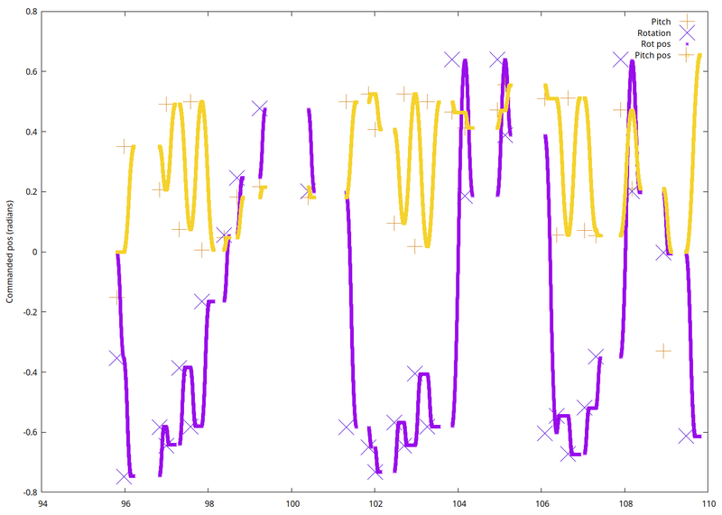
The solution I devised was to use a graph: make fake stepper motors in software and report all the motions that they perform, then plot the whole lot against to time. The fake stepper motors accept step schedules as would be sent to the Nios microcontroller and emit log events for each step time in the schedule. I also changed the move-to command to log when it is received to the same log to compare it.
My hope was to find a bug where the steppers misplaced some steps over time or something of the sort, but that was not the case.
This plot shows how the control software would move the steppers for commands sent by the cat-finder, along with the positions it is sent. The motion is in a parabolic shape due to the use of acceleration control, as expected. The steppers always arrive at the commanded positions, so whatever was observed on the bench was some kind of electronics problem or strange problem in the cat-finder.
I found one of each, one electronics problem of absent decoupling capacitors
(possibly also just the DRV8825 being a rubbish IC design, which I replaced
with a TMC2209 as soon as I got a spare), and one bug in the cat-finder where
it was sending NaNs, which probably were not doing anything good to
meowzor-control, and I learned my lesson to always check for NaN at system
boundaries and report a better error to ease debugging.
The log of step times I'm plotting has the following format for which I wrote a
simple writer in meowzor-control. The fields that may be missing if the event
should not generate a point on that series will have ? filled in:
1:TIMESTAMP 2:PITCH/? 3:ROT/? 4:AXIS/? 5:DIR/? 6:ROT_POS/? 7:PITCH_POS/?
Here's some sample data used in this plot:
95.81459	?	?	0	0	-0.0019634955	0
95.81822	?	?	0	0	-0.003926991	0
95.82104	?	?	0	0	-0.0058904863	0
95.82343	?	?	0	0	-0.007853982	0
95.82554	?	?	0	0	-0.009817477	0
To take this data file and make a plot I used gnuplot, a command-line driven
plotting program. I invoked it with echo -e 'log.gnuplot\nlog.txt' | entr -r gnuplot log.gnuplot to automatically refresh when either the script or data
changed, and used an image editor (feh) with auto-refresh. The script I used
is this:
set datafile separator '\t'
set terminal pngcairo size 1400,1000
set output "log.png"
set ylabel "Commanded pos (radians)"
plot 'log.txt' using 1:2 title "Pitch" linetype rgb "#d68a2a" pointtype 1 pointsize 5, \
    "" using 1:3 title "Rotation" linetype rgb "#4c00d4" pointtype 2 pointsize 5, \
    "" using 1:6 title "Rot pos" linetype rgb "#990ceb", \
    "" using 1:7 title "Pitch pos" linetype rgb "#f5d22c"
exit
Let's break down a line:
"" using 1:3 title "Rotation" linetype rgb "#4c00d4" pointtype 2 pointsize 5, \
^^       ^^^ ^^^^^^^^^^^^^^^^ ^^^^^^^^^^^^^^^^^^^^^^ ^^^^^^^^^^^ ^^^^^^^^^^^
|         |  |                 \- yellow line colour |           \-  pixel size of points
|         |  \- data series title                    \- plus-sign shaped points
|         \- x values in column 1, y values in column 2
\- use same file as last series
Plotting is an extremely valuable technique which I should definitely use more while debugging, especially given how easy it is to make files full of numbers to put into gnuplot. Any system involving numbers or time really benefits from drawing some kind of picture while debugging it. It took about two hours to conceive and write the mock system and get a final plot out of it which was absolutely worth it for the unambiguous answer to "how is the system performing": seems well behaved.
NixOS port
The port is available here.
Well, this is sure burying a lede. I ported NixOS to the board and it was a really really good idea and saved me a load of time. Things that I gained by porting NixOS included:
- One-command deploys of everything including system configurations and new
meowzor-controlversions (and the building of such) - One-command SD image generation
- Ability to patch things and have definitely-reproducible builds
- Easy to hack up the operating system to make it smaller
It took about a week of work on and off. The motivation for the NixOS port was that the board vendor had last released a port of Ubuntu 18.04 and I would literally rather port a new OS than deal with old OS versions and lack of config management and inability to fix the image.
Then, there was no question of which OS I wanted to port: I wanted something I could rip everything out of easily and patch anything arbitrarily if needed. Theoretically I could have used Yocto but I looked at it briefly and it looked kinda like Nix But With Extra Ways To Have Incremental Build Mistakes, and more importantly I didn't want to learn it.
I read through the Cyclone V GSRD (Golden Software Reference Design), which is an Intel port of Yocto to another board based on the Cyclone V, which should be very close to what I needed.
The main part about a port to a new board is getting the thing to boot. Once it's booted you're basically home free.
Background: Cyclone V SoC boot process
The Cyclone V SoC can boot in several different ways depending on how the
BSEL pins are configured. This is broken out to an unpopulated DIP switch on
the bottom of the DE1-SoC board, and the configured state is to boot off of an
SD card.
When reset is deasserted, a boot ROM on the hard processor performs early hardware initialization, bringing up the CPU, and chain loading from some storage, in this case, a partition of a specific MBR type on the SD card.
See the Cyclone V Hard Processor System Technical Reference Manual, appendix A, for more details on the early boot process.
This partition contains the U-Boot SPL (second phase loader), which brings up the DDR3 main memory, serial port, and some other hardware, before chain loading into U-Boot itself.
The FPGA fabric configuration port is accessed in various ways depending on
how the MSEL mode selection pins are set. On the DE1-SoC board, they are
exposed as a DIP switch set on the bottom of the board. Note that surprisingly,
MSEL[3:0] = 4'b0000, which you want, means all the switches set to
ON. This setting corresponds to FPPx16 with no encryption (fast parallel
programming), which is what works with U-Boot.
From U-Boot, the FPGA configuration image may be loaded into the configuration port. This can also be done through Linux at runtime using the FPGA Region device tree entry.
U-Boot will then chain load Linux, which NixOS supports well, so the boot process is very standard from there.
To get U-Boot to do so automatically, you need a snippet like the one below in
your U-Boot Kconfig file. This will load a script if present, then enable the
FPGA bridge, and boot Linux through the standard extlinux.conf mechanism.
CONFIG_USE_BOOTCOMMAND=y
CONFIG_BOOTCOMMAND="if ext4load mmc 0:2 ${scriptaddr} /boot/u-boot.scr; then source ${scriptaddr}; fi; bridge enable; run distro_bootcmd"
The port
The first order of business was to get a kernel that worked. I looked at the GSRD, found the config I was supposed to use, then manually built a new kernel with the checkout of the kernel sources.
I then put that kernel into the minimal image from the board vendor and confirmed it booted. Success! Next, to build it with Nix.
Building a kernel with a custom config looks something like this in Nix (full version):
{ stdenv, buildLinux, linuxKernel, ... } @ args:
let base = buildLinux { ... };
in linuxKernel.manualConfig {
  inherit stdenv;
  inherit (base) src version;
  configfile = ./socfpga_kconfig;
  allowImportFromDerivation = true;
}
It complained at build time about some missing options required by systemd, so I added those manually to the Kconfig in my checkout (see the README of de1-soc-nixos for exact details) and copied it back.
Next, U-Boot. This was not a fun time but not because of Nix. I built U-Boot
per the instructions on the GSRD guide, but using socfpga_de1_soc_defconfig
instead of the one for the different board. I replaced the U-Boot in the same
vendor image, and it would start, flash the transmit LED briefly, and not emit
anything over the serial port. Concerning, since the SPL is supposed to emit
some log lines over serial.
I was about to figure out how to use OpenOCD before I was too baffled by OpenOCD and simply googled the problem out of frustration.
After googling it a lot I wound up finding a forum thread about getting U-Boot to work on the DE1-SoC, in which someone posted a device tree patch to set the clock frequency of the UART. I applied this patch to my U-Boot development tree and, suddenly, console!! Rejoicing ensued before immediately sending the patch upstream so this never happens to anyone else.
At this point I knew both my U-Boot and Linux kernel worked, so it was time to build a NixOS SD card image. This was one of the reasons I was excited to use NixOS for this project: if an SD card fails, I can just make a new image in 30 seconds; the system image is totally disposable.
NixOS already has a SD card image builder sort of supporting U-Boot, but it does such support by leaving a gap to let the user put U-Boot in at the start of the disk after the fact. That wasn't quite satisfying enough for me because setting partition types and dd'ing things is effort and also I want to flash the image directly out of Nix build output.
I hacked this image builder up to generate the correct partition table directly and also copy the U-Boot SPL image into place.
At this point I was pretty confident that my NixOS system was going to just work when I booted it, since every part of the early boot was tested, so I just had a go and it worked. For ten seconds. Until it reset itself.
I was suspicious of power issues or some horrible crime being done to the hardware, so I removed the pieces surrounding the problematic time at boot such as resizing the root partition. This changed nothing and eventually I noticed it seemed to be based on time that the system was up. I got out a stop watch and it was a round number. After thinking about it for a minute or two I put two and two together and realized that Linux must not be correctly configured to pet the watchdog, whereas U-Boot might have been?
A quick comparison of the device trees used by the GSRD with the quite old ones
used by the upstream DE1-SoC port in U-Boot yielded some slightly different
watchdog configurations, namely, having the watchdog0 node marked as status = "disabled" (which means that it is ignored as if it is not present at all!).
This seemed suspicious. I removed that override in a patch, added the patch to
my U-Boot Nix build, and rebuilt the image:
---
 arch/arm/dts/socfpga_cyclone5_de1_soc.dts | 4 ----
 1 file changed, 4 deletions(-)

diff --git a/arch/arm/dts/socfpga_cyclone5_de1_soc.dts b/arch/arm/dts/socfpga_cyclone5_de1_soc.dts
index b71496bfb5..1cef1c2e8a 100644
--- a/arch/arm/dts/socfpga_cyclone5_de1_soc.dts
+++ b/arch/arm/dts/socfpga_cyclone5_de1_soc.dts
@@ -78,7 +78,3 @@
 	clock-frequency = <100000000>;
 	u-boot,dm-pre-reloc;
 };
-
-&watchdog0 {
-	status = "disabled";
-};
--
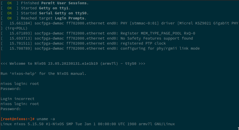
..... and it works:
How is the watchdog broken anyway?
During the project I just yolo'd fixing the watchdog because I had better things to do than root-cause it. I investigated the watchdog issue out of curiosity while writing this post.
A brief primer on status in device trees: if the status property is not
present, that means "okay". If it's present with any value except
"okay", the device will be ignored as if it's not present. This exists to
derive device trees for specific systems from a general device tree for a whole
class of systems: to remove something, it can just be marked disabled.
Thus, if a watchdog is marked status = "disabled", it does not disable (render
inert) the watchdog, it disables knowing about the watchdog. Hmm.
When the system boots, the boot ROM will enable watchdog 0 with a timeout of a couple of seconds (Cyclone V HPS TRM, page A-26). If the SPL/preloader doesn't take over the watchdog in time, the system will try the next preloader image (of the four identical copies). Thus, U-Boot needs to be doing something to take control of the watchdog or else it would not work.
Let's figure out what that is exactly.
Here are the relevant options' states:
CONFIG_WDT unset: Don't use the device tree for watchdogsCONFIG_SPL_WDT unset: Don't use the device tree for watchdogs in SPLCONFIG_SPL_WATCHDOG=y: Enable watchdog support while building SPLCONFIG_HW_WATCHDOG=y: Enable simplified watchdog support (seems to imply!CONFIG_WDTsince petting a device tree based watchdog uses the "software watchdog" path forWATCHDOG_RESET(), which is either "hardware" or "software")CONFIG_DESIGNWARE_WATCHDOG=y: Build the Synopsys DesignWare watchdog driver.CONFIG_WATCHDOG_TIMEOUT_MSECS=10000: Hardcoded timeout for the watchdog timer for use withHW_WATCHDOG.
If CONFIG_WDT, corresponding to enabling watchdog drivers in the device tree,
is unset, the Synopsys DesignWare watchdog driver (as used by the socfpga
system) will be built as a trivial version that doesn't have
a driver model so doesn't look at the device tree. That explains why the device
tree has no influence on U-Boot: the code to care about watchdogs in the device
tree is not built.
This would line up with things exploding when we arrive in Linux: the device tree is not describing the real state of the system. However, what is U-Boot doing to that watchdog peripheral, given that it seems to be on?
According to the README.watchdog, someone should be calling
hw_watchdog_init if U-Boot is to initialize the watchdog to an enabled state.
The implementation of this for the DesignWare watchdog is to take the watchdog
at the hardcoded address CONFIG_DW_WDT_BASE and set the timeout to
CONFIG_WATCHDOG_TIMEOUT_MSECS We find a call to initialize the watchdog
here on the socfpga platform when CONFIG_HW_WATCHDOG is set,
so that explains why the watchdog was initialized. If it were not set, the
watchdog would be hard-reset and rendered inert.
If Linux thinks the watchdog hardware is unused due to the state = "disabled"
in the device tree it's using, it won't pet the watchdog, which explains why
the watchdog was resetting the system after 10 seconds (the configured
timeout!). Because there's no device tree for this board in the Linux tree,
only in U-Boot, I didn't bother setting Linux to load a separate device tree,
so Linux is just receiving the verbatim device tree that U-Boot used.
Thus, setting watchdog0 to "okay" in the U-Boot device tree causes Linux to
stop being rebooted by the watchdog, since it knows to pet it, rather than not
knowing it's there at all.
Conclusion
That was a lot of work but I'm really proud of what we built. I unfortunately learned way more abyssal nonsense than I bargained for about Intel tools, but that happens every time. Having made this NixOS port is undoubtedly going to be very useful in the future if/when I have to do more projects with this board and makes it a greatly more useful device for other repurposing.
The stepgen crate is pretty great, and I would use that again. It's quite
easy to do stepper control from Rust, which is brilliant. Steppers were
mostly as easy as expected, but certainly required a fair amount of software to
correctly drive.
Given the time constraints, unknowns and already having one, the Intel FPGA development board was probably the right platform to build this thing on. Nevertheless the Intel tools were a constant impediment. I think that on future projects I will continue to do my best to chop as much as possible out of the FPGA parts simply due to how awful the development cycle is for anything including the hard processor. Definitely worth doing a lot of validation if practical before the debugging process involves building bitstreams, because 6 minute iterations are unacceptable.
It's a shame that Intel tools are so frustrating, because the hard processor is an amazingly useful feature: you can make everything that isn't a real-time problem into a Linux problem, and the ease of setting up fast shared memory with a fast microcontroller simplifies a lot of things.
My main regret is as always the project scheduling, but this happens a lot, and is never helped by external deadlines.
